Logic Pro User Guide for Mac
- Welcome
- What’s new in Logic Pro
-
- What is Logic Pro for Mac?
- Logic Pro project basics
- Undo and redo edits
- Download additional sound packs
- How to get help
-
- Tracks overview
-
- Create tracks
- Create tracks using drag and drop
- Create tracks using existing channel strips
- Assign tracks to different channel strips
- Choose the default region type for software instrument tracks
- Select tracks
- Duplicate tracks
- Rename tracks
- Change track icons
- Change track colors
- Reorder tracks
- Zoom tracks
- Replace or double drum sounds
- Control timing with the groove track
- Use selection-based processing
- Edit track parameters
-
- Overview
-
- Before recording software instruments
- Play software instruments
- Record software instruments
- Record additional software instrument takes
- Overdub software instrument recordings
- Spot erase software instrument recordings
- Use Note Repeat
- Replace software instrument recordings
- Record to multiple software instrument tracks
- Record multiple MIDI devices to multiple tracks
- Record software instruments and audio simultaneously
- Use step input recording techniques
- Record MIDI messages from another music app
- Route MIDI internally to software instrument tracks
- Use the metronome
-
- Arranging overview
-
- Regions overview
- Select regions
- Select parts of regions
- Cut, copy, and paste regions
- Move regions
- Add or remove gaps
- Delay region playback
- Loop regions
- Repeat regions
- Resize regions
- Mute and solo regions
- Time stretch regions
- Reverse audio regions
- Split regions
- Demix MIDI regions
- Join regions
- Create regions in the Tracks area
- Change the gain of audio regions in the Tracks area
- Normalize audio regions in the Tracks area
- Create aliases of MIDI regions
- Convert repeated MIDI regions to loops
- Change the color of regions
- Convert a MIDI region into a pattern region in Logic Pro for Mac
- Replace a MIDI region with a Session Player region in Logic Pro for Mac
- Convert audio regions to samples for a sampler instrument
- Rename regions
- Delete regions
-
- Chords overview
- Add and delete chords
- Select chords
- Cut, copy, and paste chords
- Move and resize chords
- Loop chords on the Chord track
- Transpose chords
- Edit chords
- Work with chord groups
- Use chord progressions
- Change the chord rhythm
- Choose which chords a Session Player region follows
- Analyze the key signature of a range of chords
- Analyze the chords in audio or MIDI regions in Logic Pro for Mac
- Extract vocal and instrumental stems with Stem Splitter
- Create groove templates
-
- Overview
-
- Add notes
- Select notes
- Snap items to the grid
- Move notes
- Copy notes
- Change the pitch of notes
- Resize notes
- Edit note velocity
- Quantize the timing of notes
- Quantize the pitch of notes
- Change note articulations
- Lock the position of events
- Mute notes
- Change note color
- View note labels
- Delete notes
- Time stretch notes
- View multiple MIDI regions
- Split chords
- Automation/MIDI area in the Piano Roll Editor
- Open other editors
-
- Session Players overview
- The Session Player Editor
- Choose a Session Player type and style
- Chords and Session Players
- Choose Session Player presets
- Regenerate a Session Player performance
- Follow rhythm of chords and other tracks
- Work with Drummer multi-channel kits
- Convert Session Player regions into MIDI or pattern regions
-
- Logic Pro for Mac advanced editors overview
-
- Audio File Editor overview
- Play audio files in the Audio File Editor
- Navigate audio files in the Audio File Editor
-
- Audio File Editor edit commands
- Edit audio files with transient markers
- Use the Audio File Editor Pencil tool
- Trim or silence audio files
- Remove DC offset
- Set audio file levels
- Normalize audio files
- Fade audio files
- Reverse audio and invert phase
- Audio File Editor Loop commands
- Undo Audio File Editor edits
- Backup audio files
- Use an external sample editor
-
- Mixing overview
- Set channel strip input format
- Set channel strip pan or balance positions
- Mute and solo channel strips
- Reorder channel strips in the Mixer
-
- Plug-ins overview
- Add, remove, move, and copy plug-ins
- Search for plug-ins in the Mixer
- Insert a plug-in on a track using drag and drop
- Activate plug-ins on inactive channel strips
- Use the Channel EQ
- Work in the plug-in window
- Work with plug-in settings
- Work with plug-in latencies
- Work with Audio Units in Logic Pro for Mac
- Use MPE with software instruments
- Use the Plug-in Manager
- Work with channel strip settings
- Surround panning
- Use the I/O Labels window
- Undo and redo Mixer and plug-in adjustments
-
- Smart Controls overview
- Show Smart Controls for master effects
- Choose a Smart Control layout
- Automatic MIDI controller assignment
- Map screen controls automatically
- Map screen controls
- Edit mapping parameters
- Use parameter mapping graphs
- Open the plug-in window for a screen control
- Rename a screen control
- Use articulation IDs to change articulations
- Assign hardware controls to screen controls
- Compare Smart Control edits with saved settings
- Use the Arpeggiator
- Automate screen control movements
-
- Live Loops overview
- Start and stop cells
- Work with Live Loops cells
- Change loop settings for cells
- How the Live Loops grid and Tracks area interact
- Edit cells
- Edit scenes
- Work in the Cell Editor
- Bounce cells
- Record a Live Loops performance
- Change Live Loops grid settings
- Control Live Loops with other devices
-
- Global changes overview
- Control transposition with the Pitch Source parameter
-
- Tempo overview
-
- Smart Tempo overview
- Use free tempo recording
- Choose the Project Tempo mode
- Choose the Smart Tempo setting
- Use Smart Tempo with multitrack audio
- Work in the Smart Tempo Editor
- Improve the tempo analysis using hints
- Correct tempo analysis results using beat markers
- Protect Smart Tempo edits by locking a range
- Match audio recordings to the project tempo
- Match the project tempo to an audio region
- Use audio file tempo information
- Sync audio to a video hit point
- Record tempo changes
- Use the Tempo Interpreter
- Use the tempo fader
- Control project volume
-
- Overview
- Add notes to a score
-
- Part box overview
- View score symbols
- Select score symbols
- Add notes and rests
- Add notes and symbols to multiple regions
- Add key and time signature changes
- Change the clef sign
- Add dynamic marks, slurs, and crescendi
- Change note heads
- Add symbols to notes
- Add trills, ornaments, and tremolo symbols
- Add sustain pedal markings
- Add chord symbols
- Add chord grids and tablature symbols
- Add bar lines, repeats, and coda signs
- Add page and line break symbols
-
- Select notes
- Move and copy notes
- Change note pitch, duration, and velocity
- Change note articulations
- Quantize the timing of notes
- Restrict note input to the current key
- Control how ties are displayed
- Add and edit tuplets
- Override display quantization using tuplets
- Add grace notes and independent notes
- Delete notes
- Use automation in the Score Editor
-
- Staff styles overview
- Assign staff styles to tracks
- Staff Style window
- Create and duplicate staff styles
- Edit staff styles
- Edit staff, voice, and assign parameters
- Add and delete staffs or voices in the Staff Style window in Logic Pro for Mac
- Copy staffs or voices in the Staff Style window in Logic Pro for Mac
- Copy staff styles between projects
- Delete staff styles
- Assign notes to voices and staffs
- Display polyphonic parts on separate staffs
- Change the staff assignment of score symbols
- Beam notes across staffs
- Use mapped staff styles for drum notation
- Predefined staff styles
- Share a score
-
-
- Key commands overview
- Browse, import, and save key commands
- Assign key commands
- Copy and print key commands
-
- Global Commands
- Global Control Surfaces Commands
- Various Windows
- Windows Showing Audio Files
- Main Window Tracks and Various Editors
- Various Editors
- Views Showing Time Ruler
- Views Showing Automation
- Main Window Tracks
- Live Loops Grid
- Mixer
- MIDI Environment
- Piano Roll
- Score Editor
- Event Editor
- Step Editor
- Step Sequencer
- Project Audio
- Audio File Editor
- Smart Tempo Editor
- Library
- Sampler
- Drum Machine Designer
- Step Input Keyboard
- Smart Controls
- Tool Menu
- Control Surface Install Window
-
- Logic Pro projects
- Various windows
- Controller Assignments window
- Control bar
- Tracks area
- Global tracks
- Automation
- Live Loops grid
- Mixer
- MIDI Environment
- Piano Roll Editor
- Score Editor
- Event List
- Step Editor
- Step Sequencer
- Flex Time
- Audio File Editor
- Smart Tempo Editor
- Surround Panner
- Channel EQ
- Space Designer
- Sampler
- Touch Bar shortcuts
-
-
- Working with your control surface
- Connect control surfaces
- Add a control surface to Logic Pro for Mac
- Automatic assignment for USB MIDI controllers
- Grouping control surfaces
- Control Surfaces settings overview
- Modal dialog display
- Tips for using your control surface
- Supported control surfaces
- Software and firmware for Logic Pro for Mac
-
-
- Environment overview
- Common object parameters
- Customize the Environment
-
-
- Fader objects overview
- Use fader objects
- Play back fader movements
- Work with object groups
- Fader styles
- Fader functions: MIDI events
- Fader functions: range, value as
- Fader functions: filter
- Vector fader
- Special faders overview
- Cable switchers
- Meta event faders
- SysEx faders
- Work with SysEx messages
- Special functions
- Ornament objects
- MMC record buttons
- Keyboard objects
- Monitor objects
- Channel splitter object
- Physical input objects
- Physical input objects
- MIDI click objects
-
-
- Use MIDI plug-ins
-
- Arpeggiator overview
- Arpeggiator control parameters
- Note order parameters overview
- Note order variations
- Note order inversions
- Arpeggiator pattern parameters overview
- Use Live mode
- Use Grid mode
- Arpeggiator options parameters
- Arpeggiator keyboard parameters
- Use keyboard parameters
- Assign controllers
- Modifier controls
- Note Repeater controls
- Randomizer controls
-
- Use Scripter
- Use the Script Editor
- Scripter API overview
- MIDI processing functions overview
- HandleMIDI function
- ProcessMIDI function
- GetParameter function
- SetParameter function
- ParameterChanged function
- Reset function
- JavaScript objects overview
- Use the JavaScript Event object
- Use the JavaScript TimingInfo object
- Use the Trace object
- Use the MIDI event beatPos property
- Use the JavaScript MIDI object
- Create Scripter controls
- Transposer controls
- Record MIDI to Track
-
-
- Alchemy overview
- Alchemy interface overview
- Alchemy Name bar
- Alchemy file locations
-
- Alchemy source overview
- Source master controls
- Import browser
- Source subpage controls
- Source filter controls
- Source filter use tips
- Source elements overview
- Additive element controls
- Additive element effects
- Spectral element controls
- Spectral element effects
- Pitch correction controls
- Formant filter controls
- Granular element controls
- Sampler element controls
- VA element controls
- Wide unison mode
- Source modulations
- Morph controls
- Alchemy master voice section
- Alchemy Extended parameters
-
- ES2 overview
- ES2 interface overview
- ES2 integrated effects processor controls
- Use ES2 in Surround mode
- Extended parameters
-
-
- Sample Alchemy overview
- Interface overview
- Add source material
- Edit mode
- Play modes
- Source overview
- Synthesis modes
- Granular controls
- Additive effects
- Additive effect controls
- Spectral effect
- Spectral effect controls
- Filter module
- Lowpass, bandpass, and highpass filters
- Comb PM filter
- Downsampler filter
- FM filter
- Envelope generators
- Mod Matrix
- Modulation routing
- Motion mode
- Trim mode
- More menu
-
- Sculpture overview
- Sculpture interface
- Global parameters
- Amplitude envelope parameters
- Use the Waveshaper
- Filter parameters
- Output parameters
- Use surround range and diversity
- Define MIDI controllers
- Extended parameters
-
- Studio Piano
-
- Ultrabeat overview
- Ultrabeat interface
- Synthesizer section overview
- Filter section controls
- Distortion circuit controls
- Glossary
- Copyright and trademarks
Channel strip controls in Logic Pro for Mac
Each channel strip has a set of controls (also called components), which varies according to channel strip type. You can adjust the channel strip volume and pan position, mute and solo channel strips, add and adjust effects, and send the output to auxiliary or output channel strips.

Audio Device controls: The following audio channel strip controls are visible when a compatible audio interface is connected. See your audio interface user guide for more information.
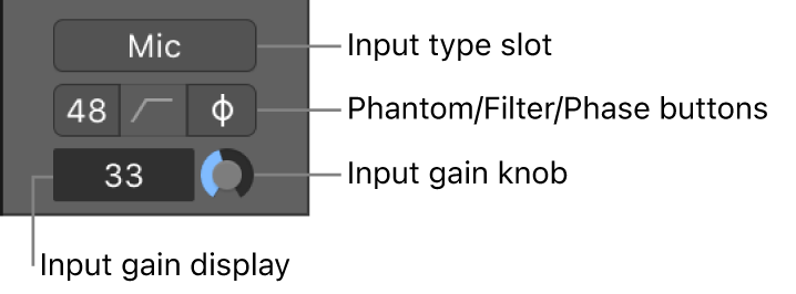
Input type slot: Choose the type of audio device connected to the input, for example microphone, instrument, line level equipment, and so on.
Phantom power button: Sends phantom power to an attached microphone. Check your microphone documentation to determine if your microphone needs phantom power.
Filter button: Activates a low-cut filter across the input. This can reduce the amount of low-frequency rumble recorded, if present in the source signal.
Phase reverse button: Use this button to reverse the phase of the audio signal. This can be useful when recording the same signal with multiple microphones. When the button is lit, the phase is reversed.
Input gain field: Displays the amount of input gain added to the audio signal.
Input gain knob: Use to set the amount of input gain.
Direct hardware monitoring button: Activates or deactivates direct hardware monitoring for the channel. This allows you to hear your recorded material without the latency incurred by monitoring your signal through Logic Pro. See your audio interface’s documentation for details on how it implements direct hardware monitoring.
Setting button: Use to load, browse, or save channel strip settings for the selected track. These settings represent the entire routing configuration of a single channel strip, including plug-ins and their settings. See working with channel strip settings.
Gain Reduction meter: Displays the gain reduction of the first Compressor plug-in, or (if no compressor is inserted), the gain reduction of an inserted Limiter or Adaptive Limiter plug-in on the channel strip.
EQ display: Do any of the following:
Click to insert a Channel EQ into the first unused Insert slot, or to open or close (if already open) the topmost inserted Channel or Linear Phase EQ.
Option-click to insert a Channel EQ into the first slot and move any inserted plug-ins down one slot.
Shift-click to insert a Linear Phase EQ into the first unused Insert slot.
Option-Shift-click to insert a Linear Phase EQ into the first slot and move any inserted plug-ins down one slot.
Command-click to remove the topmost Channel EQ or Linear Phase EQ plug-in.
You can use EQ effects to shape an audio signal by adjusting specific frequency range levels. See Use the Channel EQ.
MIDI Effect slot: Inserts a MIDI effect into the software instrument channel strip. See Use MIDI plug-ins.
Input/Instrument slot: On audio channel strips, choose an input channel of the selected audio device or bus (depending on the channel mode) from the Input slot. On instrument channel strips, choose a software instrument plug-in from the Instrument slot.
Audio Effect slot: Inserts an audio effect into the channel strip. Use effects to alter signals in real time. See Overview of plug-ins.
Channel Mode button: Switches the channel strip input format between mono and stereo. Click and hold to see a menu of all options, including Left, Right, and Surround format.
Send slot: Routes the signal to an aux channel strip. The Send Level knob that appears defines the amount of signal to route. Use sends to process effects for multiple signals at the same time. See Send a mix to multiple destinations in Logic Pro for Mac.
Send Level knob: Controls the amount of signal sent to an aux channel strip. Use sends to process effects for multiple signals at the same time.
Output slot: Choose the channel strip’s output destination—where the channel strip signal is sent to. You can also choose the output type, and pan or balance type.
Group slot: Controls a channel strip’s group assignment. Use the Group Settings window to define which parameters are controlled for the entire group at once. See Overview of groups.
Automation Mode button: Sets how channel strip and plug-in changes are handled during recording and playback. See Choose automation modes.
Track icon: Displays the track icon of the track assigned to the channel strip. You can change the track icon in the track header, or in the Track inspector when the track is selected.
Pan/Balance knob: Sets the channel strip signal’s position. On mono channel strips, it controls the signal’s left/right position. On stereo channel strips, it controls the balance between the left and right signals. In surround and Spatial Audio projects, the knob changes to a surround panner or 3D Object Panner. See Set channel strip pan or balance positions.
VCA slot: Assigns the channel strip to an existing VCA group. See Use VCA groups in the Mixer.
Peak level display: Updates during playback to show the highest peak level reached. Red indicates a level above 0 dB that is clipping. Orange indicates a level above 0 dB that is not clipping because of internal floating point processing. Click to reset all peak level displays.
Volume fader position field: Shows the position of the Volume fader. To move the fader position, double-click, then enter a position value.
Volume fader: Adjusts the playback volume of the channel strip signal.
Level meter: Shows the level of the input signal—when playing an instrument or singing, for example. Amber and yellow signals are safe. Red indicates signal clipping.
Record Enable button: Makes the track or channel strip ready for recording.
Input Monitoring button: Allows you to hear incoming audio on audio tracks that aren’t record-ready. Use to set audio levels or to practice parts before recording.
Note: When a channel strip input is set to No Input, the Record Enable and Input Monitoring buttons on the channel strip are dimmed, indicating that these buttons can’t be used (have no impact).
Bounce button: Used to bounce the output of an output channel strip to an audio file.
Mute button: Silences the channel strip signal so that it isn’t heard during playback.
Solo button: Isolates the channel strip signal so that it’s heard alone during playback.
Dim button: Lowers the level of output channel strips by the Dim value set in Logic Pro > Settings > Audio > General.
Track Name field: Shows the track name and track color. Double-click to enter a new name for the channel strip.
Choose which channel strip controls to display
You can choose which channel strip controls you want displayed on channel strips by doing one of the following:
In the Logic Pro Channel Strip Components or MIDI Channel Strip Components submenus of the Mixer > View menu, choose a control to display, or deselect a control to remove it.

Control-click a portion of a channel strip not containing a channel strip control and in the Channel Strip Components submenu of the pop-up menu choose a control to display, or deselect a control to remove it from channel strips.

Choose Configure Channel Strip Components from the Mixer > View menu, the channel strip pop-up menu, or press the Configure Channel Strip Components key command and choose which controls you wish to display.
Save a configuration of channel strip controls as default
In Logic Pro, choose Configure Channel Strip Components from the Mixer > View menu or Control-click a channel strip and choose Configure Channel Strip Components from the pop-up menu.
Choose Store as User Defaults from the Actions menu.
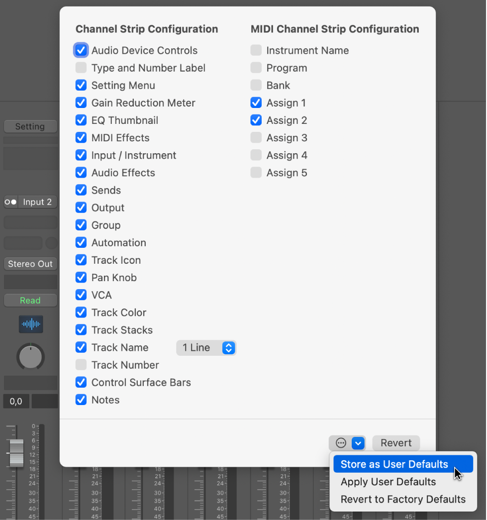
Apply a saved configuration of channel strip controls to the Mixer
In Logic Pro, choose Configure Channel Strip Components from the Mixer > View menu or Control-click a channel strip and choose Configure Channel Strip Components from the pop-up menu.
Choose Apply User Defaults from the Actions menu.
Revert channel strip controls to default settings
In Logic Pro, choose Configure Channel Strip Components from the Mixer > View menu or Control-click a channel strip and choose Configure Channel Strip Components from the pop-up menu.
Choose Revert to Defaults from the Actions menu or click the Revert button.
Download the guides:
Logic Pro User Guide: PDF
Logic Pro Instruments: PDF
Logic Pro Effects: PDF
Control Surfaces Support Guide: PDF